Three Point Bending Geometry for the DHR Rheometer
General Information
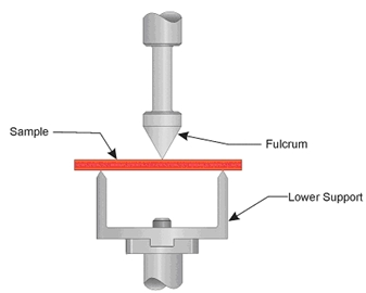
The three-point bending geometry supports a solid rectangular sample in the horizontal position. The sample ends rest upon the support attached to the motor, while the transducer applies force to the center of the sample. The sample is bent around a fulcrum held by the transducer, with the transducer applying a small amount of static bending force. The sample is therefore tested under a static bend.
Following placement of the sample onto the lower geometry, the fulcrum should be positioned to touch the sample with a minimum amount of force. This will enable the DHR to accurately control the static stress in the sample and ensure that the fulcrum is always in contact with the sample throughout the entire test (as the sample modulus changes).
Either the constant force or force tracking modes of an Axial Force mode should be used with the three-point bending geometry. Force tracking mode used in temperature and time/cure sweeps offers the advantage of allowing a wider modulus range to be tested, since force tracking mode adjusts the static load on the sample as the material softens or hardens.
Applicable Environmental Systems
Furnace (ETC)
Available Sizes
The following are the available frame sizes for three point bending:
Frame = 10 mm, 25 mm, 40 mm
Recommended Sample Dimensions
You can choose between three support frames: 10 mm, 25 mm, and 40 mm. The following rectangular sample dimensions (that fit within the physical constraints of the geometry) are recommended:
- L = Up to 50 mm (depends on the frame size selected)
- W = Up to 12.7 mm
- T = Depends on complex modulus
Sample Testing Limits
The sample dimensions define the testing range, which is the instrument operating range where useful data can be expected. If the required sample dimensions are not physically practical, then an alternate geometry should be selected.
Note that the modulus of the test sample at test temperature has a significant effect on the available operation range. A single point test with the desired geometry should be used to fine-tune sample parameters and geometry selection. If too much force is required or the measured strain is significantly lower than the commanded value (which indicates that the transducer compliance may be too large to accurately correct), the sample should be made thinner or narrower to obtain better results. Any slight errors in geometry measurement can produce errors in modulus data, but will not affect temperatures of transitions within the sample.
The ETC is a radiation oven with the solid sample and temperature probe in different locations - thus the actual temperature of sample and probe may be different. The difference varies with the sample thickness and the applied heating rate. In this case the furnace temperature needs to be calibrated in order to monitor the correct sample temperature(see alsoOffset and Span Calibration for DHR/AR).
Installing the Geometry and Loading the Sample
Installing the Geometry
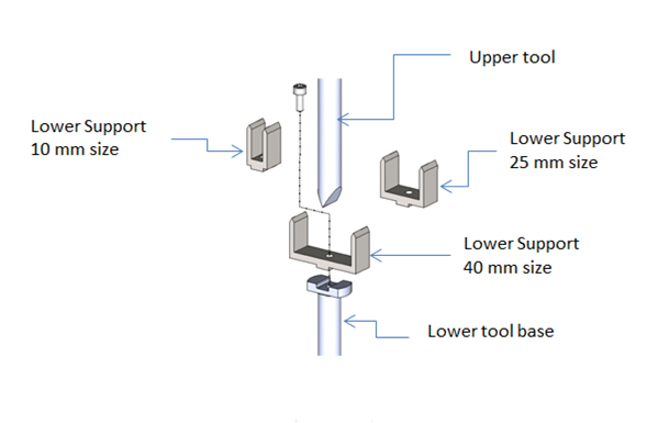
Follow these instructions to install the geometry. Refer to the figure below for geometry component identification.
- Use the Raise to loading gap button to raise the head.
-
Install the lower smart swap geometry with the 25 mm frame attached. Install the alignment tool onto the frame.
-
Attach the upper geometry and tighten the draw rod ( See also Fitting a Geometry on the DHR/AR). Note that the upper clamp is not a smart swap geometry.
- If this is the first time you are using this geometry, use the Geometry Wizard to configure and define the parameters for this geometry. Otherwise, select the appropriate geometry from Geometry on the Experiment tab.
-
Using the Down button on the keypad, lower the upper geometry into the V slot on the alignment tool. Tighten the draw rod. In TRIOS, set the gap to zero from the Instrument panel with the Tare button.
-
Next, run the axial mapping calibration from the File Manager >Geometries > Calibration. Use the Read Alignment Position to set the alignment position.
- Manually move the upper geometry to allow it to rotate freely. On the Instrument Motor panel, align the upper geometry with the Move to alignment position
 button. Then click Calibrate to perform the axial mapping.
- Raise the head to provide room to load the sample. Remove the alignment tool and mount the 10 mm or 40 mm frame to the base, if required.
Loading the Sample
Refer to the figure below for an illustration of the geometry with a sample loaded.
- From the Motor Instrument panel, click the Move to alignment position button to align the upper test fixture.
- Center the sample onto the lower geometry fulcrums.
-
Adjust the stage position to bring the fulcrum to the sample. Apply a small normal force manually or activate axial force control. See also Axial Force Guidelines.
Recommendations for Setting Up the Procedure
- Before starting the test procedure, make sure that the test fixture is aligned and locked.
- If temperature tests are to be performed, use axial force control from the Instrument Control panel to preload the sample before starting the test and insert a Conditioning Options step in the procedure to maintain the axial force control during the test.
Equations
Strain Constant

|
Stress Constant

|
Shear Factor
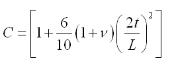
|
Variables
W= Width of sample (mm)
T= Thickness of sample (mm)
L= Length of sample (mm)
|
